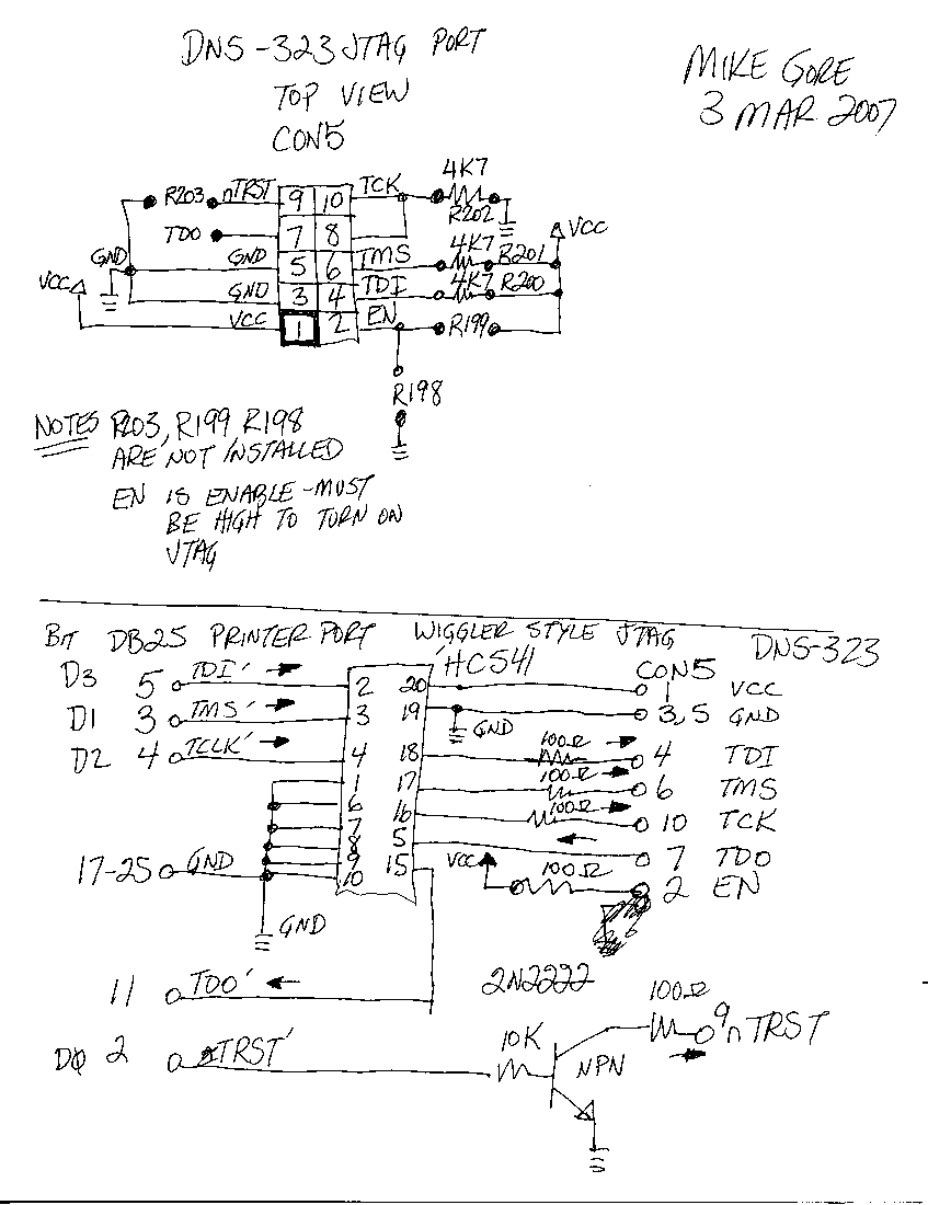
JTAG port on the DNS-323
WARNING: attaching a JTAG port will certainly void your warranty and could destroy your unit.
Please feel free to update, cleanup or correct this page.
What is this?
This document shows how to use the JTAG port on the DNS-323.
Requisites
- You need openocd OpenOCDinstalled on a linux box
- You can get the sources svn checkout svn://svn.berlios.de/openocd/trunk
- You need a JTAG cable
Two types of jtag cables are discussed here: 1: The “Wiggler” style, which is basically a conversion between the jtag interface on the embedded system and the parralel (printer) port on your PC. 2: The “Amontec JTAGKey Tiny” (other commercially models may or may not work), which provides a USB connection at the PC side. Comparison: pro method 1: cheaper, Pro method 2: less soldering (faster?)
JTAG Pinout Reference
TOP VIEW Note Pin 1 is square pin
| Signal | Pin | Pin | Signal |
|---|---|---|---|
| sRST | 9 | 10 | TCK |
| TDO | 7 | 8 | TCK |
| GND | 5 | 6 | TMS |
| GND | 3 | 4 | TDI |
| Vcc | 1 | 2 | nTRST |
Note nTRST must be sent a buffered high signal to use JTAG
Be aware that this pinout seems to be based on the DNS 323 version B2 and the CH3SNAS. The DNS-323 version A1 has the same space for a header, but the location of the surrounding resistors is different. This might or might not have consequences for the validity of the pinout as above. (Anyone: more information on the A1 rev.?) Rev A1 is the same pinout, smd resistors are already attached, just add header.
JTAG Interface scheme for DNS-323 with the Wiggler port
openocd configuration file for the Wiggler method
openocd.cfg
cat openocd.cfg
#daemon configuration
telnet_port 4444
gdb_port 3333

#interface
interface parport
parport_port 0x378
parport_cable wiggler
#parport_cable old_amt_wiggler
jtag_speed 1
#use combined on interfaces or targets that can't set TRST/SRST separately
#reset_config trst_and_srst srst_pulls_trst
#reset_config trst_only
#reset_config trst_and_srst combined
reset_config srst_only

#jtag scan chain
#format L IRC IRCM IDCODE (Length, IR Capture, IR Capture Mask, IDCODE)
jtag_device 4 0x1 0xf 0xe

jtag_nsrst_delay 1200
jtag_ntrst_delay 1200

#target <type> <endianness> <chainpos> <variant>
target feroceon little 0

# planing with flash code - work in progress
working_area 0 0x00400000 0x40000 nobackup

#          driver   addr       size     chip_width  bus_width  options
flash bank cfi      0xff800000 0x400000 1           2          0

#target configuration
init
reset run
sleep 500
halt
JTAG Interface scheme for DNS-323 with the Amontec JTAGKey Tiny
Solder 47 KOhm resistors @ R202 R201 R200 Connect JTAG pins just like the Wiggler port, and also bridge R199 (EN pin to VCC) to enable JTAG. Refer to the top half of the pdf as attached in the previous section. Pinout of the jtagkey tiny is available here
openocd configuration file for the Amontec JTAGKey Tiny
openocd.cfg
telnet_port 4444
gdb_port 3333

interface ft2232
ft2232_device_desc "Amontec JTAGkey"
ft2232_layout jtagkey
ft2232_vid_pid 0x0403 0xcff8
jtag_speed 3

reset_config srst_only
jtag_device 4 0x1 0xf 0xe

jtag_nsrst_delay 1200
jtag_ntrst_delay 1200

#target <type> <endianness> <chainpos> <variant>
target feroceon little 0

# planing with flash code - work in progress
#working_area 0 0x00400000 0x40000 nobackup

#          driver   addr       size     chip_width  bus_width  options
flash bank cfi      0xff800000 0x800000 1           2          0

#target configuration
init
reset run
sleep 500
halt
OpenOCD
Running OpenOCD
- Start the program
openocd -d3 --log_output log.txt
- Telnet to the debug interface
telnet localhost 4444
Trying 127.0.0.1...
Connected to localhost.
Escape character is '^]'.
Open On-Chip Debugger
- Memory dump of the U-Boot flash
> mdb 0xfffd0000 0x10
0xfffd0000: 12 00 00 ea 14 f0 9f e5
0xfffd0008: 14 f0 9f e5 14 f0 9f e5
- Dump Marvell» U-BOOT prompt in firmware example
> mdb 0xfffea826 0x8
0xfffea826: 72 76 65 6c 6c 3e 3e 20
- Reset CPU
 Target 0 halted
target halted in ARM state due to debug request, current mode: Supervisor
cpsr: 0x200000d3 pc: 0x00f12a2c
MMU: disabled, D-Cache: disabled, I-Cache: enabled
TODO
- The flash code in OPENOCD does not understand CFI mode 2 access. However this looks to be easy to fix. There is an early patch that attempted to address this but was never added into the project release. This code provides a good starting point.
