This is an old revision of the document!
How to add a serial port
WARNING: attaching a serial port will certainly void your warranty and could destroy your unit.
Serial connector
- The serial connector is at CON4, a white connector inbetween the two drive leds.
- This is a 3.3V TTL serial port, common on many hardware devices.
- You CAN NOT connect it directly to a PC serial port, you will need a
level shifter, a popular (and simple) chip for this is the MAX323.
Pinout on the NAS
- Warning: Do not use 5v signals - you might damage the CPU
- With the power button facing you and component side up
- Reading left to right
^Pin 1^Pin 2^Pin 3^Pin 4^
|3.3V|TX|RX|GND|
Correction 30 nov 2008
| Pin 1 | Pin 2 | Pin 3 | Pin 4 |
|---|---|---|---|
| 3.3V | RX | TX | GND |
Correction here is wrong. You should always use direction depending on device which You describe. First post was correct. Agree. Just to emphasize correct pinout: Pin 2 is serial data out from DNS-323, Pin 3 is Serial data in to DNS-323
Several pictures of serial port installation on the back of the unit can be found here: http://picasaweb.google.com/rastislav.david/DNS323SerialLink#
Hardware Revision C1
If you own a dlink323 hardware revision C1, than the board layout looks a bit different. Take a look on this picture
A - J is the JTAG and 1- 4 is the serial panel.
Hardware Layout C1
| Pin 1 | Pin 2 | Pin 3 | Pin 4 |
|---|---|---|---|
| 3.3V | RX | TX | GND |
3.3V has to be connected to VCC, if you have a level converter. You see, it's the same ![]()
Pin2→ PC RX - DNS TX, Pin3→ PC TX - DNS RX
Serial Connection Using A Nokia Data Cable
Perhaps the cheapest/simplest way to connect to the DNS-323 via its serial port is to get your hands on a Nokia CA-42 or DKU-5 data cable. These cables already contain electronics necessary to interface between RS-232 and USB, and cheap knock-offs are readily available for a few dollars on eBay, buy.com, dealextreme, etc. For complete details on adapting one of these cables for this purpose, please see http://buffalo.nas-central.org/wiki/Use_a_Nokia_Serial_Cable_on_an_ARM9_Linkstation and http://www.uchobby.com/index.php/2009/10/04/diy-usb-to-serial-cable-for-3/.
Your finished cable will have a USB A connector on one end and either three or four wires on the other (RX, TX, GND, and possibly power). Whether or not the power line is needed depends on the specific design of the circuitry within the cable (note that the housing around the USB connector is longer than normal to accommodate this circuitry). In cables where the phone powers the circuitry (in this case, think of our DNS-323 as the phone), the power line will be present. On the other hand, the circuitry within the cable may be powered directly from the USB port; in these cables, the power line will be absent. Regardless of which design you have, you'll need to install a USB serial port driver on your computer before attaching your cable to the DNS-323. Separate the wires (we don't want any shorts!) and plug the USB connector into your computer. Windows will detect new hardware and ask for a driver. Instructions for downloading and installing Prolific's USB serial driver are at http://www.plugapps.com/index.php5/Hardware:_Pogoplug_Pro_Serial. After the driver is installed, use Device Manager to verify/adjust the settings of your new serial port (port number, baud rate, etc).
Now all that remains is to connect the wires to the serial interface connector on your DNS-323 as described elsewhere on this page, fire up PuTTY or a similar terminal program and – if everything is wired correctly – voila! You now have console access to your DNS-323! If you have any doubts about whether your cable is correctly wired, you might want to first run a simple loopback test before connecting it to your DNS-323 (see links above for the details).
Other Ways to Make A Serial Cable
Turning a Nokia data cable into a serial cable is cheap and simple. However, there are many ways to accomplish the same goal, and instructions for assembling similar cables from scratch are provided below:
Parts Used
- I bought the connectors from Digikey
- Digikey WM1722-ND female housing and WM1775-ND pins (= MX51021-0400 + MX 50079/50058)
- Digikey MAX3232ECPE+-ND 16 pin dip part (note the odd +-ND suffix is correct)
Terminology
- TX is the outgoing 3.3 volt CMOS signal FROM the Marvell 88F5181 ARM CPU
- RX is the ingoing signal TO the CPU.
Data Rate
- Baud rate is 115200 baud - 8 bits, no parity and no flow control.
If properly connected, you will see several messages during boot time. You need to break into the shell to type commands, as you could do in a normal ssh or telnet session.
Breaking into a shell
- Magic code to break into shell is 5784468 followed by the enter key
- I looked at the ash.c source - see busybox-1.00-pre1/shell/ash.c - Look for is_interactive
U-BOOT
- See U-BOOT Monitor
Serial to TRS (mini stereo)
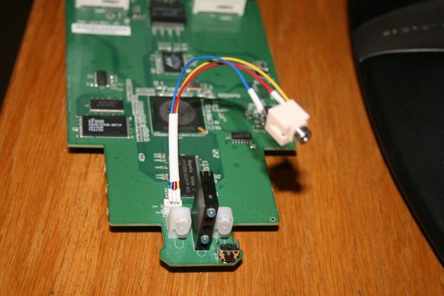
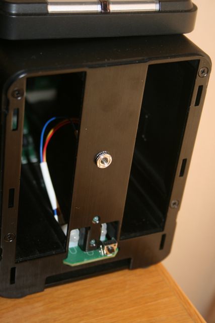
A very simple way of extending the serial port to an accessible position is to make a connector from the on-board header to a mini stereo (TRS) socket, then mount the socket behind the face plate of the DNS-323. This helps to preserve the original appearance of the unit, as the socket is only visible when the front face plate is removed as if to add a new drive.
You can then use an FTDI USB->Serial adapter to connect it to the PC. Of course, something like the Nokia CA-42 cable (or a cheap clone) can easily be retrofitted with a suitable mini-stereo plug as well, which is what I ended up doing.
This diagram shows how FTDI wire up their connectors. It probably makes sense to do the same if you repurpose a CA-42 cable.
Here are some shots of how I mounted mine:
Building your own RS232 level adapter
If you are used to electronics and prefer doing things by yourself, you can build you own level converter. Go to Serial_level_adapter
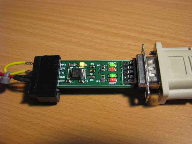
Using bkamen's RS232->Logic adapter
Forum User 'bkamen' is an electronics designer and made some RS232 to logic board for his lab and some clients as well as anyone else who needs them. They come already assembled with a 3V-5.5V MAX3221, DE-9 connector and indication LED's – ready to solder to the board with some wire. In the image below, you can see the signals coming off the end of the board. Just solder to them. (_INV_ isn't used in this appplication)
Using the Futurlec board
Futurlec makes a board at http://www.futurlec.com/Mini_RS232_TTL_3V.shtml that can be used to perform the level conversion. This is one way to go. It can even be mounted in the center brace. Here is one way to go, if you really want a serial port. Note that the Futurlec board was shipped from Thailand for me and took about 4 weeks to get to me via post, so you may want to pick a more expedient shipping method.
- Get the following items from Digi-Key (http://www.digikey.com):
- WM1722-ND Conn Housing 4Pos 1.25MM. I'd get a few, in case you mess up.
- DM1775-ND Conn Term Female 28-32AWG Tin. You need a few of these, I'd get plenty to mess up with. It's hard to get those connectors on right.
- 621K-ND Bracket RT Ang Mont 4-40 Steel. This is used to mount the Futurlec board to the brace.
- H342-ND Screw Machine Phillips 4-40×1/4. Screws for attaching the thing, these go into the angle bracket.
- 3157K-ND Washer Flat #4 .120x.312 Nylon. Insulated washers are a good idea against the circuit board.
Some of them have large minimum orders, like 100, but the whole thing cost me $16.42 with shipping. You will also need:
- 30AWG wire. This is a lot easier to get into the connectors than standard wire.
- External 2 USB plate. These should be easy to find at a computer store. You want one that has the 4-connector flat connectors that plug into a motherboard. The connector should have a square location that you can use to press to remove the pins from the connector. These will plug into the Futurlec board.
- RJ45 female connector that will hook onto the panel. I'm not sure what these are called, but I had some so I used them. Note that you can use an RJ11 or RJ12, if you like, but you need to buy everything else accordingly. The RJ11 might be better; I can't close the front with the RJ45.
- Flat cable, 4, 6, or 8 conductor depending on which connector you choose, with the proper RJxx male connectors on each end.
- A RJxx to 9-pin connector. You can find these at some computer stores. Fry's and Microcenter both have them.
- Some shrink-wrap.
The procedure:
- Cut the cables from each USB connect so you are left with the 4-pin flat connector and a length of wire. Cut the cable back
some and strip the wires.
- Cut 4 small lengths of the 30AWG wire, strip one end of each and solder each of them on to the wires from one of the former USB cables.
- Shrink-wrap the solder joints to avoid shorts.
- Strip the other end of the 30AWG wire very short, perhaps 1mm.
- Crimp a DM1775-ND onto each of the 30AWG wires. This is rather hard and detailed, make sure they are compact so they will go into the connector. Note that the 30AWG wire will not take being bent over and over, so take care especially when plugging it in.
- You need to make sure you get the wiring right. These all go to the 6-pin connector on the Futurlec board. The TX from the DNS-323 (pin2) goes to TX, RX to RX, +3V to +3V, and GND to GND. Note that you will need to remove the GND wire from the 4-pin connector and put it on the GND pin (see pictures). The 4-pin connector will hang off the end a little.
- Take the other former USB connector, and strip back the outer shield. Do not strip the wires. Instead, they will be pressed into the RJxx female connector.
- You need to spend some time and figure out all the wiring. Then you can press the wires into the RJxx connector in the proper locations so they will match up with the output of the Futurlec board.
- Ohm-out the cables to check for shorts and connectivity. This is important. Double-check your wiring.
- Build the RJxx cable and converter to 9-pin. Again, wiring planning is a little tricky.
- Now plug everything in and test it. Make sure to not put the board onto a metal surface.
- It should work. If not, check wiring. Note that I had one unit that I burned the TX line on due to a short. So be careful and test the cables.
- On the front plate, measure where the RJxx connector will go and use a chisel to break out a section. This is rather hard. I used a chisel, drilled some holes, and inserted a coping saw, and sawed around where the chisel made the impression. Note that the panel is aluminum, so it is very easy to bend. So be careful.
- Drill holes in the front plate for the board to mount. Make sure there is room for it and the RJ45 and that it won't interfere with internal components. The spacing is a little tight, so measure.
- Put the RJxx connector through, and mount the board. When mounting, use the nylon washers on both sides of the circuit board. Put it all back together and test again.
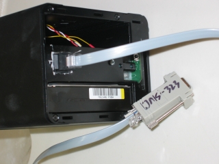
Here's two pictures of the panel 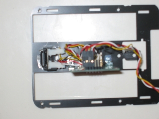
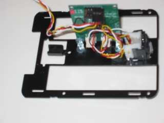
Here's a picture of the inside. Note that I have way too much wire, so don't do that :) 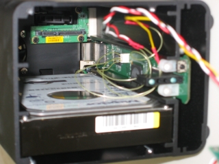
Using a USB cable
If you do not have a serial port on your computer, FTDI sell a convenient USB cable that contains a serial chip and level converter in one, and has bare wires at the other end. The cable has drivers for all major operating systems, I am running it under linux with no problems. The datasheet is here. This is what i used:
- DigiKey 768-1016-ND USB cable and logic converter (TTL232R3V3)
- Digikey WM1722-ND female housing (Molex 51021-0400) and WM1775-ND pins (Molex 50058-8000)
Just solder the wires to the connector in this order:
| Pin 1 | Pin 2 | Pin 3 | Pin 4 |
|---|---|---|---|
| Red | Yellow | Orange | Black |
When using the USB to Serial adapter with the DNS-323, you may have to disconnect the red (power) lead from the connector. On the Rev. A1 of the board, once the USB connector is plugged into a computer, it may power up the DNS-323 mainboard and start the boot process without the powerbutton being pushed. Once the red lead was disconnected, the DNS-323 wouldn't start until the power button was pushed, thereby allowing the complete boot sequence to be viewed.
datasheet link is modifed to here.

